Engineering 11 – Electrical Circuit Analysis
Lab
#2
9/28/03
Diodes
and Demodulation
Aron Dobos &
Adem Kader
Abstract
In
this experiment, the electrical characteristics of diodes and capacitors were
observed and applied in practical contexts.
Applications of the aforementioned components for transforming
alternating current to direct current as well as in signal demodulation areas
were explored. The measurements obtained
conclusively verified the correct functioning of the diode, and confirmed its
utility in everyday circuitry
Introduction
Diodes
are circuit elements that allow current to flow through them in only one
direction. They have two terminals
called the anode and cathode, and are represented schematically by the
following symbol:

Current
flows only from the anode to the cathode with ideally no voltage drop. In practice, however, diodes generally create
approximately a 1 volt potential drop across the terminals. Equations describing the electrical characteristics
of diodes will be discussed later. In
terms of practical applications, diodes are frequently used to transform a
sinusoidal alternating current (AC) signal into direct current (DC). Consider the following circuit:
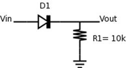
This
circuit is called a half-wave rectifier.
If a sinusoidal alternating current is applied to Vin,
the diode will only allow currents flowing in the positive direction to pass
through. Therefore, the current measured
at Vout will always be positive, but it will be 0 when the input
current is negative.
To
smooth out the choppy output current, a capacitor can be used. A capacitor is a circuit element that can
store a certain amount of electrical charge and release it at a later point. Suppose we wired a capacitor in parallel with
the 10kΩ resistor:
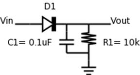
When
the diode allows current to flow, the capacitor accumulates a certain amount of
charge. When the
current changes polarity, the capacitor releases its stored charge over a short
period of time, keeping the current at Vout from reaching 0 quickly. Depending on the choice of capacitor, very
smooth DC output currents can be achieved.
Another
useful application of diodes and capacitors can be found in AM radios. AM stands for amplitude modulation, and it is
a technique by which a relatively low frequency electrical signal (for example,
a signal representing audible sounds) can be modulated with a high frequency
"carrier" signal that can travel long distances. The trick is to decode the modulated signal
at a receiving station. A demodulator
circuit that looks exactly like the one depicted above can accomplish the
translation given appropriate choices for the resistor and capacitor
values. Consider the rectified signal
below:
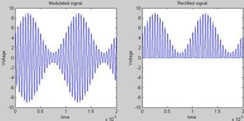
By
carefully choosing a capacitor that will smooth out the signal between peeks,
the original input signal can be accurately recreated. However, if the capacitance chosen is too
small, the transformed signal will be fuzzy, and if too big, significant signal
detail will be lost as well.
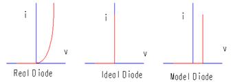
Theory
The
electrical characteristics of real-world diodes can be represented by the
current-voltage relationship indicated below
i = Is * ( e^(
40 * v / n ) - 1 )
where v is the voltage across the diode. Note that when v is positive, the current
through the diode is large. However,
when v becomes negative, the
exponential term goes to 0, leaving i = Ia - 1 . For analysis
purposes, we will only use the diode model represented in the second two graphs
included below.
Capacitors
can store an amount of charge that is directly proportional to the capacitance
and the voltage across the terminals: Q =
C*V. It takes time for a
capacitor to accumulate charge and to release it, so the current is the
derivative with respect to time of the charge.
It follows then that
ic
= C * (dv / dt)
With
regards to amplitude modulation and demodulation, suppose the input signal is
of the form
Vi(t) = A + B
* sin( ws * t )
Since
this signal Vi must be modulated to a high
frequency, we can multiply it with some high frequency carrier signal
Vc(t) = sin( wc * t )
to get the final modulated signal
Vm(t) = (A + B * sin( ws * t )) * ( sin( wc
* t ) ) .
To
calculate the appropriate capacitance required for the demodulator, we can use
the following equation
R * C = A
/ ( ws
* B )
where A is the
value of the input signal voltage when the derivative of the signal is
greatest, B is the difference between A and the peak of the input voltage, and ws is the frequency of the
input signal. This equation is arrived
at using
![]()
which is the equality for the two maximum
decreases in the wave. Using the above
equality and assuming Tc<<τ, a
R * C = A
/ ( ws
* B )
Using
a resistance of 10 kΩ, a capacitor of 0.030 mF was calculated
as an acceptable capacitance (the calculation can be seen in the Results
section).
Procedure
The
attached procedure was followed for this lab.
Due to some
technical problems with the oscilloscope, some of our results are distorted and
not clear.
Results
Graph 1:
Graph 1 shows the initial regular sine wave and the modulated sine wave.
Graph 2:
This graph shows the demodulated signal. On the graph (as can be seen in the table under the graph) V1(2) and V2(2) show the values of (A + B) and (A – B) respectively. A and B are the coefficients we will use to find C.
A + B = 5.6 V ß V1(2)
A – B = 1.6 V ß V2(2)
Thus,
A = 3.6 V
B = 2.0 V
From these values of A and B, C can be calculated using the following equality
![]()
Plugging in the values,
![]()
which yields,

Graph 3:
This graph shows how the alternating current is transformed into a one way (not direct) current using a diode. Since the diode lets current flow in one direction only, the negative current is set to 0 current and the positive current is left as it originally was.
Graph 4:
Graph 4 shows the change in the initial sine wave with the addition of a 1kΩ resistor and a 0.1μF capacitor.
Graph 5:
This graph shows the change in the initial signal due to the addition of a 10kΩ resistor and a 0.1μF capacitor.
Graph 6:
Graph 6 shows us the modification of the signal with a 10 kΩ resistor and a 0.2μF capacitor.
Discussion
The diode model does a good job modeling the behavior of a real world diode in our experiment. It lets no current when the AC is in the negatives and lets the current through when the AC is in the positives. As shown on Graph 3, the voltage drop between the original signal and the rectified signal when the diode allows current flow is nearly constant, meaning that the constant voltage drop diode model is a good approximation of the real world results.
The printout showing Vin and Vout with the 0.1 μF capacitor is attached (see graphs 4 and 5). When the resistance was decreased, the capacitor discharged much faster because there was a smaller resistor between the capacitor and the ground making it much easier for the capacitor to let the charge free. When the capacitance was increased, the charge stored in the capacitor increased and this resulted in the capacitor taking more time to let the stored charge free. Looking at graphs 5 and 6, this difference can be observed. Graph 6 shows us how a 0.2 μF capacitor (compared to that of graph 5 which is 0.1 μF) took more time, causing a straighter line between the two peaks, since the larger capacitance allowed more charge to be accumulated.
The output of the Wavetek generator was much more than the drop in the Exact generator because it had a much larger impedance (600Ω) compared to that of the Exact generator (50Ω).
The modulated signal was a high pitch sound because the frequency of the modulated signal was very high, and thus was nearly inaudible.
The appropriate value for the capacitor was calculated as shown in the Results section. The modulated signal and the original input are shown together on graph 1 and the modulated signal and the original signal are shown on graph 2.
Conclusion
Diodes can be
used in AC to DC current conversion applications. As a result, electricity can be sent over
long distances from power plants to people’s homes in AC, and then can be
rectified into DC currents for use in nearly all electronic devices. Also, we have shown that a relatively low
frequency audio signal can be modulated with a high carrier frequency, making
it possible to transmit the signal over long distances. Furthermore, we have also shown that a
modulated (generally high frequency) signal can be demodulated to reproduce the
original signal with significant accuracy.
This method can be used to transmit radio signals and get audible sound
by demodulation.