Engineering 11
Lab 3
First Order Time
Domain Response
Aron
Dobos, Adem Kader
October
20, 2003
Abstract
In this lab, the time-domain response
of first order transient circuits was explored.
Simple circuits involving a single capacitor and some resistors were
examined, as well as how such combinations could be used to configure the LM555
timer/oscillator integrated circuit for other practical applications. The measurements obtained confirmed the
validity of the equations used to model the circuit's behavior under stimulus,
and provided an opportunity to practice applying the appropriate first order
analysis techniques.
Introduction
Capacitors are circuit elements that
can store electrical charge when a voltage is present across its terminal. The amount of charge q that a capacitor can
store is directly proportional to the voltage v across it. The quantities are related by the
proportionality factor C, which is the capacitance (measured in farads) of the
capacitor itself.
![]()
Since current is defined by the
equation ![]() we can write the
current through a capacitor as
we can write the
current through a capacitor as![]() . Since the current
through the capacitor is the derivative of the voltage, we can note that it is
impossible to instantaneously change the voltage across the terminals of a
capacitor, since infinite power would be required. As a result, we must analyze the behavior of
circuits involving capacitors over some time period. Consider the simple circuit below:
. Since the current
through the capacitor is the derivative of the voltage, we can note that it is
impossible to instantaneously change the voltage across the terminals of a
capacitor, since infinite power would be required. As a result, we must analyze the behavior of
circuits involving capacitors over some time period. Consider the simple circuit below:
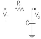
Suppose
we connect Vi to a function generator configured to output a square wave. When the square wave is high (some non-zero
voltage), the capacitor charges since a voltage is present across its
terminals. When the input voltage goes
low, it effectively becomes connected to ground and the capacitor discharges
through the resistor R. Using Kirchoff's
current law, we can write an equation for the circuit:
![]() or
or ![]()
A solution for this first order
differential equation is
![]()
We can see by the form of this equation
that the voltage across the resistor falls exponentially towards zero when the
square wave goes low. The value![]() is called the time constant, and is abbreviated in equations
by т. We will derive expressions
for the initial and final values of the voltages and the associated time
constants involved in this circuit in the next section.
is called the time constant, and is abbreviated in equations
by т. We will derive expressions
for the initial and final values of the voltages and the associated time
constants involved in this circuit in the next section.
The next first order transient circuit
experiment involves the LM555 timer/oscillator integrated circuit. The IC can be modeled simply by the following
diagram and three facts:
1.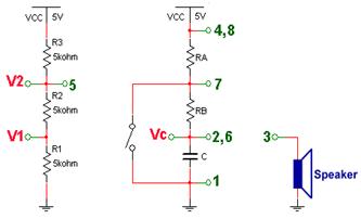
If Vc > V2, the switch
closes.
2.If Vc < V1, the switch opens,
3.If Vc is between V1 and V2, nothing
happens.
Resistors Ra, Rb, and capacitor C are
external to the IC and thus can be configured by the user. When the internal switch is open, the
capacitor C charges with some time constant.
When the voltage reaches V2, the switch closes and the capacitor
discharges through resistor Rb. When the
voltage drops past V1, the switch opens again and the process continues. This cycling effect can produce a specific
output frequency on the output pin of the IC, and thus generate a tone if
connected to a speaker. By changing the
values of Ra, Rb, and C, we can adjust the time constants of the charge and
discharge cycles and thus configure the output frequency of the oscillator.
If an external voltage is applied to
pin 5 (affecting V2), we can achieve a tone that varies over time by altering
the threshold that governs the oscillation frequency. Suppose a 0.5 Hz 1 volt peak-to-peak triangle
wave is applied to pin 5. Since the
voltage threshold for the switch increases and decreases over time, the output
frequency of the oscillator will also increase and decrease over time. The triangle wave results in a siren-like
sound when a speaker is connected to the output.
Theory
This section presents derivations of
the important equations previously mentioned.
For circuit 1, we wish to arrive at an equation for the time constant
т. We know that
т =![]()
However, the function generator is
modeled by a Thevenin equivalent with Rth = 600 ohms. Therefore,
т =![]()
The initial value of the voltage v(0)
is simply the peak to peak voltage of the square wave input from the function
generator.
![]() .
.
The final value of the voltage occurs
when the first time constant occurs.
According to our equations, that is when t = ![]() . In other words, the
final voltage occurs when the voltage difference between t = 0 and t =
. In other words, the
final voltage occurs when the voltage difference between t = 0 and t =![]() is
is ![]() That is
That is
![]() -->
-->![]()
Thus, the final voltage at the end of
the time constant period is given by
![]()
For the timer/oscillator circuit, we
must derive equations for time periods T1 and T2, as well as the final
frequency of oscillation generated as a result of the choice of Ra, Rb, and
C. To derive T1, let t = 0 be the time
at the moment that the internal switch opens.
Using our simple capacitor circuit equation![]() , we get the result
, we get the result
![]() .
.
The final value of the voltage at the
time constant is two-thirds of the maximum expected voltage across the capacitor. In this case, the maximum voltage
theoretically reached across the capacitor terminals is 5 volts, and the
initial voltage is 1/3 of the maximum, since the switch opens when Vc drops
just below V1, which is 1/3 * 5 volts by voltage division. Simplifying,
![]() -->
-->![]() -->
--> ![]()
Looking at the circuit, we see that
that total resistance is Ra + Rb, so
т = ![]() and finally
and finally ![]() .
.
To calculate T2, let t = 0 be the time
at which the switch closes and the capacitor discharges. We use our standard capacitor equation
again. This time, the initial voltage is
10/3 since that was the greatest voltage reached before the switch closed. The final voltage will be 5/3 volts, since
that is the lowest possible voltage before the switch opens again to recharge
the capacitor. Consequently,
![]() -->
--> ![]() -->
--> ![]() .
.
The resulting frequency of oscillation
is given by the reciprocal of the sum of the time differences. That is, the frequency is one over the period
that it takes for a complete charge / discharge cycle. Thus,
![]() .
.