In this laboratory experiment, we observed the solid-body rotation of a fluid in a tank at various speeds. The fluid was spun up into a full solid body rotation from a stationary initial state, and the nature of the spin-up process was observed with the aid of various markers and fluids added to the rotating drum. The fluid motion problem was compared to the simpler Rayleigh problem in order to obtain insight into how the fluid actually spins up to a steady state when it is initially at rest in the non-spinning container. The floating orientations of various cubes with specific weights less that that of water were also observed, both before and after the steady state solid body fluid rotation had been achieved in the tank.
It can readily be shown that a uniformly rotating fluid within a vertical cylindrical container has constant pressure contours that are parabolic in nature. Suppose that z denotes the vertical coordinate from the bottom of the container, and that r represents the radial one. The constant pressure surfaces are given by
where z0 is the centerline elevation of the water in the tank. Fitting the data values obtained from the spray painted water lines with a power regression of the form
we get from the graphs that m1 = 2.809, m2 = 0.00094, and m3 = 2.2861. It is clear that the quadratic model is in fact a good representation of the actual data. The curve fit results indicate the radius r is to the 2.28 power, which is essentially a quadratic fit. The center waterline value is also shown to be 2.809 cm.
The constant pressure surface equation can be rewritten to determine the angular rate of rotation from a radius and various z values as follows:
Plugging in the values r = 9 cm and z = 2.95 cm from the slow rotation, and taking z0 to be 2.809 cm, we get from the theoretical model that
The rotational frequencies were measured to be 5.12 seconds per rotation for the slow speed, and 2.11 seconds for the fast speed. For the slow rotation, we calculate w as follows:
As one would expect, these values for the angular rate of rotation are close to each other, and the discrepancy can be accounted for by the fact that the exponent in the best power fit was 2.28 rather than 2. Note that the density of the fluid does not appear in the constant pressure contour equation, and consequently it does not affect the result.
The way in which the fluid in the tank actually spins up to a solid body rotation from stationary state cannot be solved in closed form. The Rayleigh problem exhibits much simpler geometry but still provides insight into what might be happening. Suppose a body of liquid represented as a stack of finite "sheets" of fluid that interact via shear forces on their adjoining surface areas. When the surface upon which the fluid rests begins moving, each layer of liquid pulls on the one above it, causing the whole fluid body to eventually move. The solution to this problem is a second order differential equation known as the diffusion equation. Solving the diffusion equation yields the Complementary Error Function, given as
The last step is simply a linear approximation, and it is shown in the laboratory exercise assignment to be a reasonable approximation for small values of Eta.
Supposing z = 1 cm, we can calculate based on the Rayleigh problem solution approximately how long it takes for the velocity of the fluid to reach 95% of its final value. Plugging in the appropriate values, we discover that it takes 12732 seconds, or 212 minutes. For z = 7 cm, we get an astounding 623887 seconds, or approximately 173 hours. Clearly the Rayleigh problem does not fully account for what is happening in the tank, considering that the experimentally measured spin-up times were approximately 6.5 minutes for both speeds.
The huge discrepancy might be partially explained by the differences in geometries of the two situations. In the spinning tank, the difference between the velocity of the water at the bottom and at the top of the fluid mass along with the different radial velocities (greater at the outside edge) cause a cross-sectional "churning" that induces a mixing of the water packets. As a result, due to the greater momentum of the faster moving sections of fluid compared to slower moving ones, a significant amount of mixing between "layers" of fluid happens. This mixing effect is entirely ignored in the ideal Rayleigh problem solution, and essentially causes the slower moving fluid sections to gain momentum more rapidly, and thus for the fluid mass to spin up to steady state far faster than predicted by the diffusion equation's solution.
A variety of markers were added to the rotating tank to help ascertain what in fact was happening in the fluid mass as it spun up to steady state. Food coloring, permanganate (MnO4) solid, and reflective sprinkles were all added to indicate different aspects of the fluid motion.
A carefully dropped squirt of food coloring started going straight to bottom but then was swept away in an arc when nearing the bottom of the tank. This showed how the fluid at the bottom was moving faster due to the shear force caused by the bottom of the rotating tank. As the fluid came close to complete solid body rotation, this effect was no longer visible, meaning that all the fluid was moving cohesively, and that internal shear forces between "layers" of fluid were no longer acting.
We can also say that the food coloring showed the simplistic nature of the stacked layer model because it diffused throughout the tank rather quickly. An undisturbed still jar of water with one drop of food coloring takes overnight to fully diffuse, but by the end of the exercise the whole tank had become some ugly murky color. This means that the liquid cannot be modeled simply as contained layers, and that mixing or churning has to be happening between the layers to cause the rapid diffusion of the dye. There was also some strange swirling not at the center of the tank which also supports the idea that there is mixing happening, with smaller eddies, especially at close to the outside of the tank where the shear forces was greater due to the viscosity force caused by the rotating outside wall and the bottom. The solid permanganate showed essentially the same behavior as the food coloring.
The reflective sprinkles floating in the center were affected last by the rotating motion because in the center of the tank the water was not moving initially, but rather was spun up by the faster moving outside radial volumes of fluid. This suggests that the shear force due to outside of the tank was far greater than due to the rotating bottom. There is more influence from the walls of the tank than from the bottom of the tank because the radial acceleration is inwards towards the center.
A floating entity is said to be stable if, when displaced, it returns to its original equilibrium position. As a floating body rotates, the location of the center of buoyancy, passing through the centroid of the displaced volume, can change. As long as the center of gravity stays below the point of action of the buoyant force regardless of the rotational disturbance upon the body, the body should return to its equilibrium position.
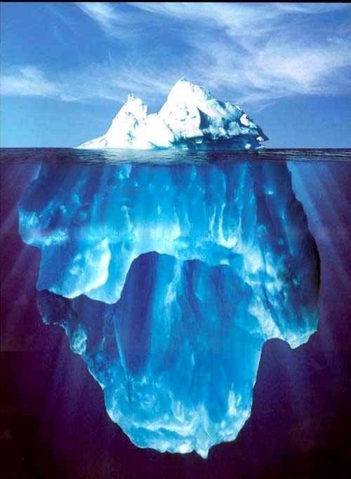
Cubes of various materials with specific weights less than that of water will float in different orientations due to the aforedescribed reasons. Depending on the density of the cube relative to water, more or less of the cube’s volume will float above the waterline. In order to keep the center of gravity below the buoyant force, the cube may float in either of the orientations depicted above. For cubes with specific weights closer to that of water, the 2nd orientation in the figure was observed. This is the "expected" orientation. Cubes with specific weights approximately half that of water floated with most of the volume below the waterline, as shown in the 1st orientation, with a pyramidal extrusion above the water line. Icebergs in the ocean float in the same fashion, with most of their mass underwater and only a small portion above.
In the spinning tank, the cubes stayed in the same orientations as in the still water. They did however take the quadratic curved waterline as base waterline, and thus floated at an angle with respect to the base of the tank, while maintaining their original "pyramid" or "flat" orientations.