Engineering 6 Bridge Report
3 May 2005
Anima Singh, Chris Harman, Molly Piels, Maisha Howard, Aron Dobos
Abstract
In this lab, a small basswood truss bridge was designed, constructed, and tested to failure. The design procedures involved developing a Multiframe truss panel model and simulating it to obtain estimates of bending moments, load distributions, and total deflections under load. Once a satisfactory design was complete, the bridge was constructed from basswood and carpenter’s glue to meet the design specifications. The completed truss bridge was tested to failure using the press shown in the picture below. The bridge held 161 pounds, and at a weight of 37 grams, had a load-to-weight ratio of 4.35 lbs/gram.
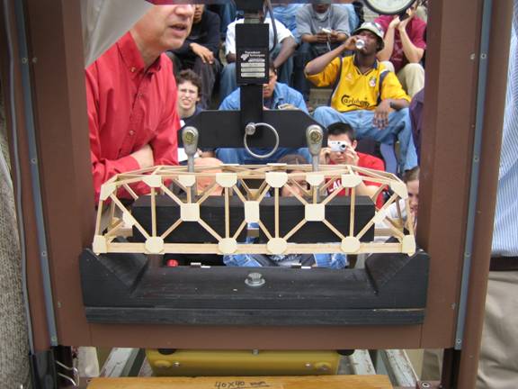
Figure 0. Bridge in the Testing Machine
Design and Simulation
Procedures
Side truss design went through four iterations. The first two designs were not drawn to scale because individual pieces of data from Multiframe runs were only relevant in how they related to other pieces of data. That is, the actual stress on a member was not important, but it was necessary to see whether or not it bore more stress than another member. The third design was drawn to scale, but used wood section data similar to basswood rather than basswood itself. Because all calculations are linear, this yielded accurate results.
To get ideas for strong, aesthetically pleasing designs, a Google image search was performed. Most trusses viewed were simple, square models, though some bore a mild resemblance to the third and final designs.
The first step in the design process was to analyze a simple box truss in Multiframe (see Figure 1). At no point was the intention to use a truss such as this one as a final design, but analyzing the simplest case showed where the most stress would be. Once it was concluded that the horizontal center sections and the outer diagonal members would bear the most load, the design was modified to shorten those members (keeping buckling to a minimum) while keeping the bridge as tall as permissible.
Figure
1. Initial design of simple box truss
with loads (in pounds) borne by each member shown.
The next design considered kept many of the components of the original box truss, but lowered the two outer joints to the lowest permissible point (see Figure 2). This succeeded in lowering the loads borne by the outer diagonal members (by shifting them to the outer vertical members), but provided no additional support to the center of the bridge. An additional design change was to double the lowest horizontal member. This lowered the loads borne by the center members a little. Load distribution at this point was asymmetrical, which had the potential to twist the bridge as it deformed, adding additional stress to the members connecting the two trusses.
The third design considered rectified this problem by adding more diagonal members. One was added in the center, and the outermost sections were modified to include two diagonal cross members rather than one. This design was successful in greatly lowering and evening out the loads borne by diagonal members, but there was still a large bending moment all across the lowest horizontal member (see Figure 3). Ultimately, due to both constraints of construction and this problem, the bottom horizontal member was tripled. The third design was the first to be modeled to-scale.
Figure
2. Second design with loads (in pounds)
borne by members shown.

Figure
3. Third design with
bending moments shown graphically.
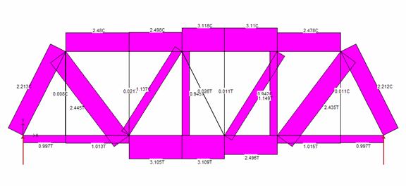
The final design (see Figure 4) further modified the diagonal members. Additional members were added in the side squares nearest the center to decrease bending moment along the bottom. The outermost diagonal members were moved to cross each other in the center. This was because Multiframe showed one of the “V” members in tension and the other in compression, which would put a lot of shear stress on the joint. While the new design did not eliminate shear stress at joints, it did lower it substantially. It was further noted that the upper horizontal members were in a lot of compression and would tend to buckle, so vertical bracings were added at the joints of “X” diagonal members. Multiframe analysis for the final design loaded at the four joints closest to the center is shown in Figures 5-8.
Figure
4. Final side truss design.
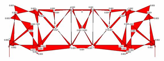
Figure 5.
Analysis of bending moment (in lbf-in) for final design under load of 0.225 kip at
each joint.

Figure 6.
Analysis of shear stress (in psi) for final design under load of 0.225 kip at each
loading joint.
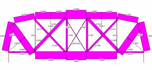
Figure
7. Analysis of load (in lbf) borne by each member under load of 0.225 kip at
each loading joint.
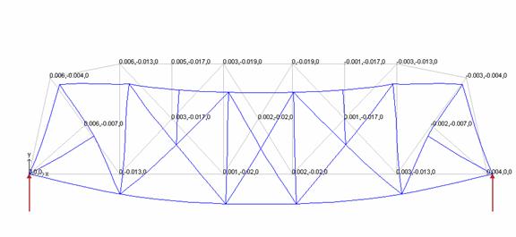
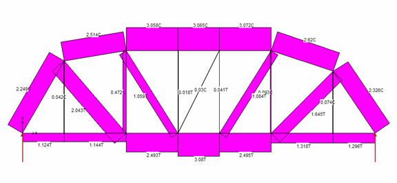
Figure
8. Analysis of expected deflection (in inches) under load of 0.225
kip at each loading joint.
Construction Methods
Three sections of square 3mm x 3mm basswood were laminated together to form the tension-bearing lower frame. The bridge was designed to transfer the load to the truss panels via two cross members per load block, and thus the design of the cross member/frame connection was vital. A notched joint was introduced to stiffen the connection. The detail of the joint configuration is shown in the figure below.
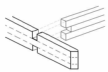
Figure 9. Frame/Cross-member Joint.
These joints were stiffened on the bottom by gusset plates to keep the beam from cracking under tension. This design was used because reports from other E6 survivors suggested that the bottom of the bridge was very important. Coupled with the fact that the basswood is worse in tension than in compression, it made sense in the design phase to make the bottom frame extra-strong. Furthermore, the transmission of load to the truss panels took place through only 8 of these joints, meaning that they had to be designed to carry significant loads without dropping out.
The construction of the truss panels was rather straightforward. Full-scale drawings were printed and the truss pieces were aligned and cut one by one as the panel was being constructed. Liberal quantities of glue were applied to the joints, and the panels were affixed to the ceiling tile with pins to maintain the proper shape during drying. Significant time was taken to ensure that pieces were in correct alignment and that angles were cut precisely. This meant that many pieces were thrown out and re-cut to ensure a quality construction. Many former E6 students had suggested to pay extremely careful attention to the craftsmanship of the bridge. A consequence of attention to detail was that the truss panels were essentially identical and individually symmetrical.
The diagonal cross-frames in the truss panel were notched at an angle and fit into each other to maintain the single-piece continuity of the members. The Multiframe simulations detected not insignificant bending moments at the intersection of these members, and as a result the notched joint was developed to help stabilize these connections. The cross-frame joint is shown below in Figure 10.

Figure 10. Cross-frame Panel Joint
Once both truss panels were complete, they were joined at the base with the cross members, and the upper bracing was put in place. A V-shaped upper cross frame was improvised to provide sufficient clearance to the load applying devices.
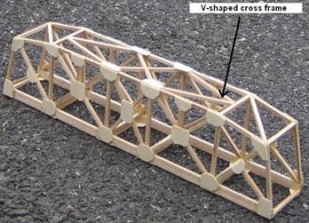
Figure 11. V-Shaped Upper Deck Frames.
The final step in the construction was to stiffen the joints by applying gusset plates with the grain going in the optimal directions. The final bridge is shown below in Figure 12.

Figure 12. Completed Bridge.
Expected Failure
Modes
Multiframe was used to analyze the possible areas of failure in the design of the bridge. A graphic depiction of the shear force (see Figure 6) shows a large amount of shear force in the upper corners of the bridge. This implies that this joint is a likely site for failure. Were this a real bridge, failure in the upper outside corners of the bridge would be more desirable than a failure, for example, in the road bed of the bridge because this would be less likely to result in fatalities. A failure as depicted in the shear force diagram would only result in falling debris.
The top horizontal member bears a large load, as does the lower horizontal member (see Figure 7). These forces however, are counteracted by the placement of the cross members, which generally do not bear enough load to fail. There is, however a large load on the outer frame of each side and the outermost cross bar. Because there is a large load on both the outer frame and the crossbar, there is no way to balance the load and the area is prone to failure.
When loaded, the center of the bridge would deflect but the outermost points would not be able to, creating more of a chance of failure at these points.
A large moment would be detrimental to any of the members of the bridge. In Figure 5, there are large moments shown at several different areas across the span of the bridge. The moments at the base were taken into consideration and the cross bars of the road bed were notched and gusset plates were added to the exterior. Another large moment can be seen at the place of predicted failure; the upper truss’s outside corner and the cross bars included in those sections. Gusset plates were added only on the sides, not at the top, of the outer frame and to the exterior of the cross bars. However, as shown by the failure, this was simply not enough.
It was concluded that the uppermost corners of the side trusses were the most likely sites of failure.
Testing Results
The finished bridge weighed 37 grams and was able to bear a load of 161 lbs before failure and had an efficiency of 4.35 lbs per gram. Under the application of load, the bridge did not undergo any noticeable deformation besides a slight deflection of the base. However, the bridge creaked under the applied load of around 80 lbs. Despite the early sign of failure, the bridge was able to hold twice that load before the side trusses failed under compression and the gusset plates cracked.
Failure Analysis
The bridge failed when the rightmost diagonal of the truss was put too much in compression. The glue and gusset holding the strut in place failed in shear, resulting in the strut “popping” out place. Assuming the failure occurred at the base of the diagonal first, a possible remedy (or at least partial remedy) for this problem would have been to notch the strut into place, disallowing it from “popping” out of place when the strut was compressed upon loading of the bridge.
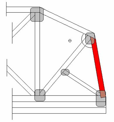
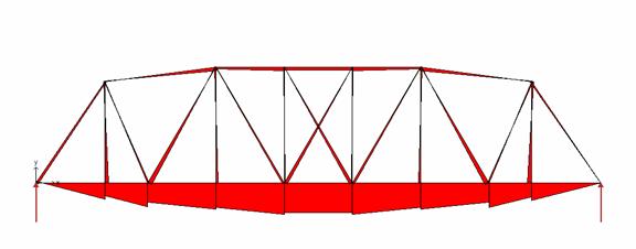
Figure 13. Failure Mode
The member colored red is the member that failed. Note the notching at the point of connection with the base of the bridge. This notching should help prevent the member from sliding out of place when loaded by limiting its rotation at the base.
The more likely cause of the failure was the inability to transfer the compressive stress in the bridge’s top-most members down to the diagonal as a result of the extreme angle shown above (Ө). To resolve this problem, it would help to implement a more gradual slope to the top of the bridge, creating a more arch-like shape better suited for distributing the compressive stresses. This quasi-arching (no actual arches were allowed in the project) combined with notching at the base of the diagonal piece that failed, would greatly improve the bridge’s load bearing ability by facilitating load distribution. Another improvement to the original design would have been gusseting the top of the frame at the point of failure to resist the large moment at the junction.
Who Did What
Overall, distribution of labor was fluid and fair. The design process was led by Aron and Molly, who were present throughout. Anima helped out the first design session when the group brainstormed, Chris the second when the group did most of its Multiframe analysis, and Maisha the third when the group finished Multiframe analysis for the third design. Since the final design was a composite of all previous designs, everyone contributed.
Immediately before the construction phase, Aron hand drew full to scale mock ups of side trusses for the group to work from. He also designed and built the bottom panel. One side panel had to be redone after the first time because the bridge was crooked. Maisha, Molly, Aron, Anima, and Chris built the first side panel together. The primary actors in building the second set were Anima, Aron, Chris, and Molly, though Maisha helped out when it did not conflict with her physics lab or sports practice. Anima, Aron, and Molly designed and built the top cross members.
Throughout the construction process, the group used various and sundry aids. Aron bought clamps and rubber bands, Chris, with vital moral support from Aron, legally and legitimately obtained an extra ceiling tile, and Molly brought extra pins.
Aron wrote the abstract, Molly wrote the first section, Aron wrote the second, Maisha and Molly the third, Anima the fourth, and Chris the fifth. This section is more or less a collaboration of all group members.
Professor Orthlieb broke the bridge, and Professor Siddiqui watched.