Engineering 72 Lab 8
Solar Seeker
Aron Dobos & Tyler Strombom
11 November 2004
Original Design
For the pen-and-paper original design document, see the attached sheet.
The original design was a very simple one implementing the standard H-bridge MOSFET motor control circuit coupled to the PIC controller through an open-collector TTL buffer. The photocell voltage is directly read by the PIC A/D. Based on the photocell voltage, the controller turns the motor in the appropriate direction, or brakes if the voltage is within a predefined dead zone. The photocell voltage is read by A/D channel 0 (pin 7: AN0), and the motor control signals come from the lower four bits of port C. The original circuit schematic is reproduced below.
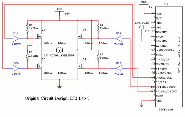
The H-bridge circuit works by controlling the direction of the current through the motor. When Q1 and Q4 are on, current flows from left to right through the motor. To reverse direction, Q1 and Q4 are turned off and Q3 and Q2 are turned on. To disconnect the motor entirely, all the transistors are turned off. In order to brake, the terminals of the motor are shorted together by leaving Q1 and Q3 off and turning on Q2 and Q4. Recalling that a high gate signal turns off a P-type FET and a low gate signal turns off the N-type, we can arrive at the truth table below:
|
|
Q1 (PC3) |
Q2 (PC2) |
Q3 (PC1) |
Q4 (PC0) |
Port C
Value |
|
Forward |
0 |
0 |
1 |
1 |
3 |
|
Reverse |
1 |
1 |
0 |
0 |
12 |
|
Stop |
1 |
0 |
1 |
0 |
10 |
|
Brake |
1 |
1 |
1 |
1 |
15 |
Thus, we simply have to write the decimal values 3, 12, 10, and 15 at the appropriate times to port C to control the motor.
To translate the 5 volt logic signals to the higher voltages needed to drive the gates of the transistors, the 7407 buffer is used in a standard configuration with 1k pull-up resistors to +14V.
No calculations were made during the design process.
The code was arrived at by combining various parts of code from lab 6. The code simply configures port C for output, pin AN0 as the A/D converter, and enters the main loop containing a 1 ms delay per iteration. The 10 bit A/D converter gives values from 0 to 1023. If the voltage is less than the center and clears the dead zone, the motor is turned on in the forward direction. If the current voltage is greater than the center value and clears the dead zone, the motor is turned on in the reverse direction. If the voltage is within the dead zone, the brake (or stop) is applied. The full source code listing is included below.
#include "PIC_A_D.h"
#byte portc=0x07
#use fixed_io(c_outputs=PIN_C0,
PIN_C1, PIN_C2, PIN_C3, PIN_C4, PIN_C5)
#define DEAD_ZONE 10
#define SAMPLES 8
#define FORWARD 3
#define REVERSE 12
#define STOP 10
#define BRAKE 15
main()
{
unsigned int16 val;
unsigned int16 ct;
unsigned int16 center;
//These next 6 lines set certain hardware on the processor.
setup_adc_ports(NO_ANALOGS);
setup_adc(ADC_OFF);
setup_spi(FALSE);
setup_counters(RTCC_INTERNAL,RTCC_DIV_2);
setup_timer_1(T1_DISABLED);
setup_timer_2(T2_DISABLED,0,1);
//Set up A/D convertor
setup_adc(ADC_CLOCK_INTERNAL);
setup_adc_ports(ALL_ANALOG);
set_adc_channel(0);
//Blink our LED (sanity check to make sure all is working).
output_low(pin_b4);
delay_ms(500);
output_high(pin_b4);
portc = STOP;
center
= 524;
while (1)
{
val = read_adc();
if (val
< (center - DEAD_ZONE))
{
portc
= FORWARD;
}
else if (val >
(center + DEAD_ZONE))
{
portc = REVERSE;
}
else
{
portc = BRAKE;
}
delay_ms(1);
// readjust every millisecond
}
}
Implementation and Testing
The above design was implemented verbatim, and proved to be a successful design. The testing involved moving flashlights, textbooks, arms, and other light intensity modifying items around the motor, and observing that the photocells always shifted to point towards the greatest light. Two video clips demonstrating the functionality of the circuit are available at
http://www.engin.swarthmore.edu/~adobos1/e72/lab8/seeker1.avi
http://www.engin.swarthmore.edu/~adobos1/e72/lab8/seeker2.avi
Final Design
The final design was identical to the original design, except that new functionality was added to allow real-time calibration of the center photocell voltage value. The code was modified to stop the motor and readjust the center value if the RB5 pushbutton was depressed. This allowed for the specification of the center voltage value without requiring the web server module or other circuitry. The relevant code modifications are listed below:
portc = STOP;
center
= 524;
while (1)
{
val = read_adc();
if (input(pin_b5)==0)
{
portc = STOP;
center = val;
}
else
{
if (val
< (center - DEAD_ZONE))
{
portc = FORWARD;
}
else if (val >
(center + DEAD_ZONE))
{
portc = REVERSE;
}
else
{
portc = BRAKE;
}
}
delay_ms(1);
// readjust every millisecond
}
Control Strategies
Two slightly different control strategies were implemented. The first one used the BRAKE signal to short out the motor leads, causing the motor stop rotating much more quickly. This resulted it relatively smooth light tracking performance, since the motor did not overshoot its target very much. With a reasonable dead zone, there was very little oscillation under normal conditions. Just using the STOP command allowed the motor to spin freely even after its power had been cut off. As a result, the motor overshot its intended target, and was forced to compensate by triggering rotation in the reverse direction. The oscillation was significant at times, with the photocells fluctuating back and forth many times before stabilizing. Luckily the oscillations always seemed to die off. This is behavior can be directly compared to the oscillator circuits and their feedback mechanisms we learned about in chapter 13 as well as E12.