Surface Mount Technology Lab Tutorial
Swarthmore College
Department of Engineering
Aron Dobos
25 May 2006
Overview
The equipment and procedures described in this document are suitable for rapid assembly of circuit boards using surface mount technology (SMT) parts. Very fine pitch high pin count ICs can be accurately placed, including packages with exposed pads on the bottom. It is assumed that no through hole parts are used, or at least that they will be mounted after the surface mount parts. The lab is located upstairs in Hicks Hall, in Professor Cheever’s research lab.
Equipment and Procedures
The general idea for mounting surface mount parts is to precisely apply a solder paste to the pads on the printed circuit board, position the components on the pads with the help of fine tweezers and a microscope, and to reflow the solder by heating the board on the hot plate. After the solder paste has reflowed, the joints can be cleaned up and any shorts removed using solder wick and a fine tip soldering iron. The solder paste is sticky enough that parts will not slide around unnecessarily once they are placed. The heating on the hot plate is not terribly localized and as a result parts that have previously been mounted might reflow. This is not a problem if the board is handled with care and the parts are not jolted around. If more localized heating is necessary, a small block of metal can be placed on the hot plate underneath the part of the circuit board needing the heating. To remove parts, simply reheat the board, and once the solder is melted, simply remove the desired part with normal tweezers. For rapid removal of resistors and capacitors, the tweezer iron can be used as well.
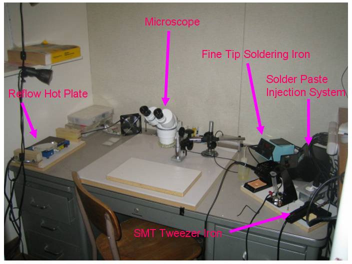
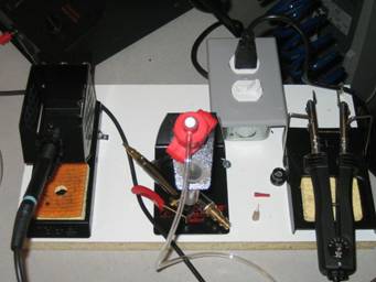
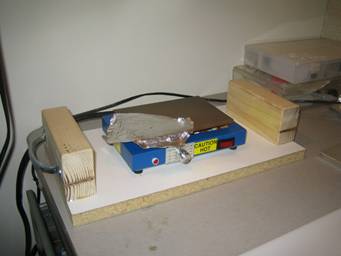
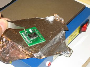
- Reflow Hot Plate: This is low profile hot plate mounted on a board with arm rests and handles that is used to reflow the solder paste by heating the circuit board from the bottom. The temperature is set usually at 270 degrees Celsius using the integrated thermostat. A piece of aluminum foil is used to protect the surface of the hot plate from unwanted solder reflowing onto the plate.
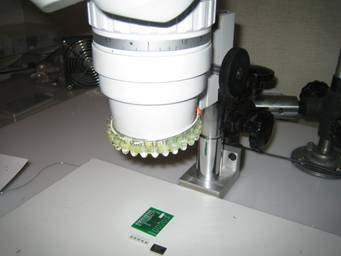
- Microscope: This stereo zoom microscope allows for precise application of solder paste, placement of components, as well as post-reflow inspection of connections. The microscope has a homemade illumination ring made of bright white leds, and is powered by the small regulated power supply located behind the microscope.
- Fine Tip Soldering Iron: Used to rework parts and to clean up excess solder from the pins. The temperature is digitally controlled, and is usually set around 700 degrees for general purpose work. After a period of inactivity, the iron cools itself to 300 degrees, and after an even longer period shuts off. To set the temperature or to remove the iron from ‘sleep mode’, simply used the up/down arrows.
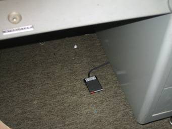
- Solder Paste Injection System: This unit uses compressed air (from an air compressor located next to the table) to apply very controlled amounts of solder paste from a syringe. The unit is controlled by a foot pedal, and can be configured in manual mode, or a timed shot-meter mode. In manual mode, solder is ejected while the foot pedal is pressed, whereas in timed mode, each press of the foot pedal ejects solder for a configurable length of time. The control unit also has a pressure regulator, as well as a vacuum system to keep solder from continuing to flow after the foot pedal is released or the shot times out. The air supply is filtered to remove particles and moisture. The solder paste is stored in its syringe in the refrigerator located in the back corner of the Hicks computer lab to extend its lifetime.
- Tweezer Iron: Used for quick removal of SMT resistors and capacitors.
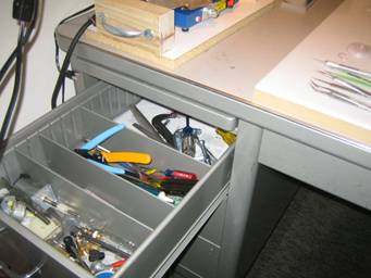
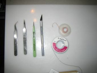
A drawer full of various useful tools is on the left side of the desk. Various fine pitch tweezers, fine solder wire, desoldering braid, and an Xacto knife are the most frequently used.
Example Board Assembly
These were the steps taken to mount a simple surface mount IC and a few resistors. The sequence is probably in more detail than necessary.
- Turn on ambient lighting attached to the wall shelves to the left of the work desk.
- Turn on the power strip mounted to wooden work bench on the right. This gives power to the various bench tools. Turn on the microscope light power supply.
- Turn the air compressor on until the pressure meter on the compressor reads about 80 psi. The compressor will stop automatically at around 100 psi if left on.
- Turn the soldering iron to about 700-740 degrees, or as desired. Wet the sponge with the squirt bottle.
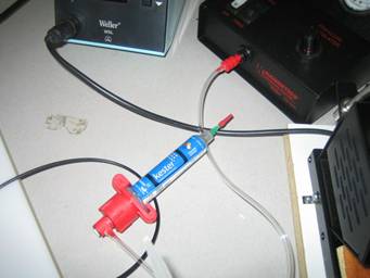
- Obtain the solder paste from the refrigerator, and connect the solder paste syringe air tube to the control unit as shown. Remove the protective syringe needle cover and place the syringe in the stand. Various sized needles are available for different purposes.

- Turn the hot plate on, and allow it to warm up.
- Focus the microscope on the circuit board using the black wheel on the right side. Generally the minimum zoom is good.
- Apply blobs of solder paste to the pads using the injector system under the microscope. Don’t worry about making a mess, the solder reflows surprisingly nicely and can be easily cleaned up. For fine pitch parts, simply apply a continuous line of paste along the pads. Usually it is simplest to use the paste injector in manual mode, but for a large number of repetitive blobs, switching to timed mode might be helpful. If the paste stops coming out, it might be necessary to increase the pressure. The pressure regulator on the control unit can be adjusted by lifting the black plastic knob and turning it. The pressure setting can be locked by pushing the black knob back down. It may be necessary to turn the air compressor on again from time to time. The vacuum knob shouldn’t require much adjustment, but it should be relatively straightforward to find an appropriate setting.
- Position the components on the pads using fine tweezers under the microscope.

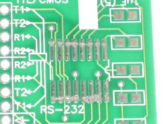
- When the hot plate is sufficiently warm, move it closer, and push the PCB down onto the hot surface using tweezers (generally with two tweezers, not shown to allow for photographing.) Push down with the tweezers in various places to localize the heating. It will be obvious when the solder has reflowed properly. The paste will have become very shiny and fluid, and will have more or less gotten sucked up onto the pins and pads. Very few shorts should remain, if any. Don’t heat the board any more than necessary, especially when using temperature sensitive parts. When the reflow is complete, transfer the PCB carefully using tweezers to a metal plate to allow the board to cool off a bit before further inspection.

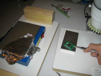

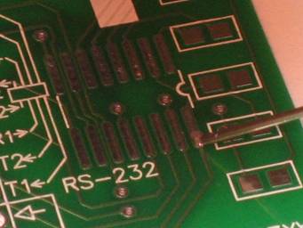
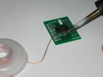
- Inspect the connections under the microscope. If a short is detected (as shown on the lower right row of pins – on purpose for demonstration), remove it by placing desoldering braid over the short, and then pushing down on the braid using the soldering iron until the excess solder has been sucked up. Make sure to use a clean section of braid, and cut off the used portions of it with a knife.
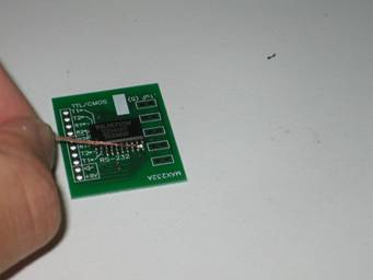
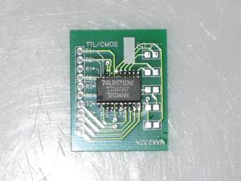
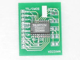
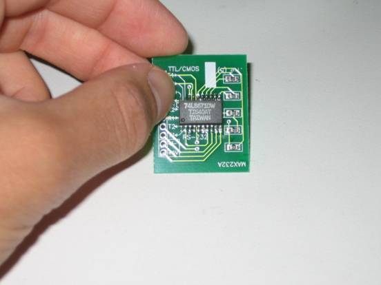
- Using the same procedures, the five resistors were also mounted. The completed demonstration board is shown below.
- Cleanup.
Cleanup Checklist
- Turn off and unplug the hot plate.
- Turn off the soldering iron, microscope illumination ring, solder injector control unit, tweezers.
- Disconnect the solder paste syringe, replace the protective needle cover, and return the paste to the refrigerator.
- Return tweezers and other hand tools to the appropriate drawers.
- Turn off the power strip on the right.
- Ensure that the air compressor is off.
Questions
Feel free to contact me at any time with questions on my cell phone or by email.

Good Luck!